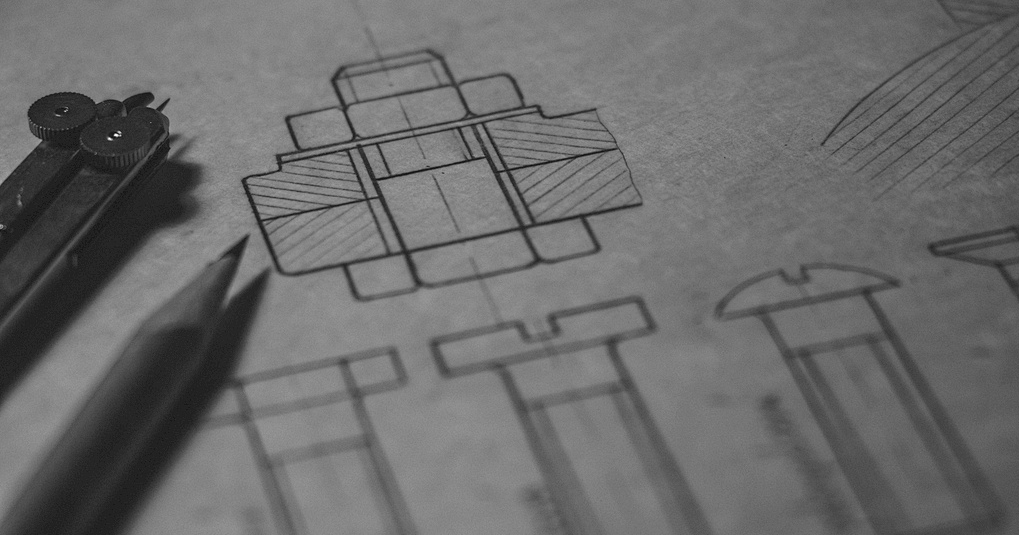
In the field of mechanical parts processing, engineering drawing is regarded as the key bridge connecting design and manufacturing. It accurately transforms the shape, size, and technical requirements of parts in the designer’s mind into intuitive drawing forms, serving as the core basis for the precise processing of mechanical parts. Next, let’s delve into the basic knowledge of engineering drawing together.
The Definition and Importance of Engineering Drawing
Engineering drawing is a specialized graphic language that uses standardized graphic symbols, lines, and annotation rules to precisely depict the geometric shape, size, positional relationship, and manufacturing technical requirements of mechanical parts. Its significance in the processing of mechanical parts is self-evident. On the one hand, it is the only accurate way for the design team to convey design intentions to the processing workshop. Through the drawings, processing personnel can clearly understand the specific appearance of each part, avoiding processing errors caused by the ambiguity of oral descriptions. On the other hand, in the quality inspection stage after the parts are processed, engineering drawings serve as the standard reference for determining whether the parts meet the design requirements and ensuring that the product quality is up to standard.
How to Draw
Preparations
Tool Selection: Traditional drawing tools include drawing boards, T-squares, triangles, compasses, pencils, etc. In the modern digital drawing environment, professional computer-aided design (CAD) software such as AutoCAD and SolidWorks is required. CAD software has the advantages of high efficiency, accuracy, and ease of modification, and has become the mainstream drawing method.
Determine the Drawing Scale: According to the size of the actual object and the size of the drawing, select an appropriate drawing scale to ensure that the drawn graphics can be clearly presented on the drawing and the layout is reasonable. For example, for large buildings, a smaller scale such as 1:100 or 1:200 may be used; for small mechanical parts, a larger scale such as 1:1 or 2:1 may be used.
Drawing Step
Layout Sketch: First, use light lines to roughly outline the main contours of the object and the positional relationships of its various parts on the drawing paper. Determine the number and arrangement of views. For complex objects, multiple views (such as the front view, top view, left view, etc.) may be needed to fully display their shapes.
Draw Contour Lines: Based on the sketch, use darker lines to precisely draw the object’s contours, paying attention to the variations in line thickness and visibility. For instance, visible contour lines should be drawn with thick solid lines, while invisible contour lines should be drawn with dashed lines.
Add Details: Gradually refine the drawing by adding details such as holes, slots, and fillets, and accurately mark the dimensions. Dimension markings should be clear and complete, adhering to relevant standards, including dimension figures, dimension lines, dimension boundaries, and arrows.
Mark Technical Requirements: Indicate the technical information of the part on the drawing, such as tolerance fits, surface roughness, and heat treatment requirements. These requirements are crucial for guiding the processing and inspection of the part.
Check and Review: After completing the drawing, carefully check the accuracy of the drawing, including the shape of the graphic, dimension markings, and technical requirements, to ensure that the drawing can accurately convey the design information.
The Basic Components of Engineering Drawings
- Drawing format: The drawing format specifies the size and specification of the drawing. Common standard formats include A0, A1, A2, A3, A4, etc. The size of A0 format is 841mm×1189mm. The subsequent formats decrease proportionally in sequence. For example, A1 is half of A0, A2 is half of A1, and so on. When choosing the drawing format reasonably, factors such as the complexity of the parts, the number of views, and the space required for dimension marking should be comprehensively considered. Determining the format before drawing the drawings is conducive to the overall layout planning, ensuring that the content of the drawings is complete, clear and the layout is coordinated. Around the drawing, a drawing frame also needs to be drawn. The format of the drawing frame is divided into two types: with binding edges and without binding edges. Each format clearly stipulates the distance from the drawing frame line to the edge of the drawing, which is the basis for ensuring the standardization of the drawing.
- Graphics: Graphics are the core of a drawing and are used to display the appearance and shape of mechanical parts. To present the parts comprehensively, a combination of multiple views is often adopted, such as the front view, top view, left view, etc. The front view is generally selected from the direction that can display the main shape features of the part, while the top view is projected vertically downward from above the part. The left view is projected from the left side of the part to the right. Each view strictly follows the projection rule of “length alignment, height level, and width equality” to ensure that the part information expressed by different views is unified and accurate. In addition to the basic view, when the internal structure of a part is complex and cannot be clearly presented only by the basic view, sectional views such as full sectional views, semi-sectional views, and partial sectional views will be introduced. Through the hypothetical sectional plane, the part is cut open to display the internal structure. There are also cross-sectional diagrams, which are specifically used to present the cross-sectional shape at a certain cutting position of a part. They are divided into out-of-section cross-sectional diagrams and coincident cross-sectional diagrams, helping processing personnel accurately grasp the internal details of the part.
- Dimensional annotation: Accurate dimensional annotation determines whether mechanical parts can be processed to the size required by the design. Dimension annotations cover elements such as dimension numbers, dimension lines, dimension boundaries, and arrows. The dimensional numbers clearly indicate the actual size values of each part of the component. The dimensional lines show the measurement direction of the marked dimensions. The dimensional boundaries define the starting and ending ranges of the dimensions. Arrows are used to indicate the measurement terminals of the dimensions. All dimension annotations must be clear, complete and reasonable. There should be no omissions, nor any repetition or contradiction. Dimensional annotation also needs to clarify the dimensional reference, which is the starting point for determining the dimensional position of each part of the component and can be divided into design reference and process reference. The design reference is determined based on the function of the part in the machine and the assembly relationship, while the process reference is set from the convenience of part processing and measurement. Reasonable selection of the size reference is crucial for ensuring the processing accuracy of the part.
- Technical requirements: The technical requirements section records key information such as the precision and surface quality of the parts during the processing. For example, tolerance fit is used to specify the allowable variation range of part dimensions, which is directly related to the tightness and fit accuracy when the part is assembled with other components. The surface roughness symbol and parameters indicate the microscopic smoothness or roughness of the part’s surface, which affects the part’s wear resistance, sealing performance and other properties. In addition, the technical requirements also include heat treatment requirements, such as quenching, tempering, annealing, etc. Different heat treatment processes will change the mechanical properties of parts such as hardness and strength. Surface treatment requirements, such as galvanizing, painting, and oxidation, can enhance the corrosion resistance and aesthetic appeal of parts. These technical requirements are important bases for processing personnel to select appropriate processing techniques and equipment.
- Title bar and Detail bar: The title bar is located at the lower right corner of the drawing and contains important information such as the part name, material, drawing scale, drawing number, signatures of the design and review personnel, and date. It is a summary description of the entire drawing and the corresponding parts. Among them, the name of the part should accurately reflect the characteristics of the part, the material label should clearly indicate the material used to manufacture the part, the drawing scale should enable the processing personnel to clearly understand the scaling relationship between the actual size of the part and the graphic on the drawing, the drawing number should facilitate the management and search of the drawing, and the personnel signature and date should record the information of the drawing design and review process. The detail column is used to list the detailed information of each part that constitutes the component, including part number, name, quantity, material, etc., facilitating the identification and statistics of parts during the processing, assembly and management of parts. For components or products composed of multiple parts, the detail column clearly presents the relevant data of each part to ensure the orderly progress of the production process.
Common Engineering Drawing Standards
- Line drawing standards: Different types of lines have specific meanings and uses in engineering drawing. For example, thick solid lines are used to represent the visible contour lines of the parts, allowing the processing personnel to directly see the shape of the parts. The fine dotted lines represent the invisible contour structure inside the part, which helps to understand the internal structure of the part. Fine dot lines are often used to represent the center lines and symmetry lines of parts, facilitating the determination of the symmetry relationship among various parts of the part and the axial position of the rotating body. The width, length and spacing of various types of lines all follow the corresponding standards to ensure the standardization and readability of the drawings.
- Scale specification: The ratio of the size of the part graphic on the drawing to the actual size of the part is called the drawing scale. Reasonable selection of the drawing ratio can make the parts clearly presented on the drawing and properly laid out. For large mechanical parts, smaller scales such as 1:5, 1:10, etc. may be adopted in order to display the overall appearance within the limited drawing space. For small and precise parts, larger proportions such as 2:1 or 5:1 May be chosen to highlight the details. In the title column of the drawing, the adopted drawing scale must be clearly marked to avoid misunderstandings about the dimensions by the processing personnel.
- The format and content filling of the title bar and detail bar are strictly regulated. The size, division of the title bar, as well as the order and position of filling in each item, all follow the standard regulations to ensure that the information is clear and neat. The arrangement of part numbers in the detail column should be orderly, starting from the top left corner and arranged in a clockwise or counterclockwise direction in sequence. The information such as part names, quantities, and materials should be filled in accurately and without error. The font and size should also comply with the norms to ensure the professionalism and standardization of the overall drawing.
Mastering these basic knowledge of engineering drawing plays a crucial role, not only in the internal communication and collaboration of mechanical parts processing enterprises, but also in the accurate communication of the design intentions of parts between customers and enterprises, laying a solid foundation for the efficient and precise completion of mechanical parts processing!